Product successfully added to quote!
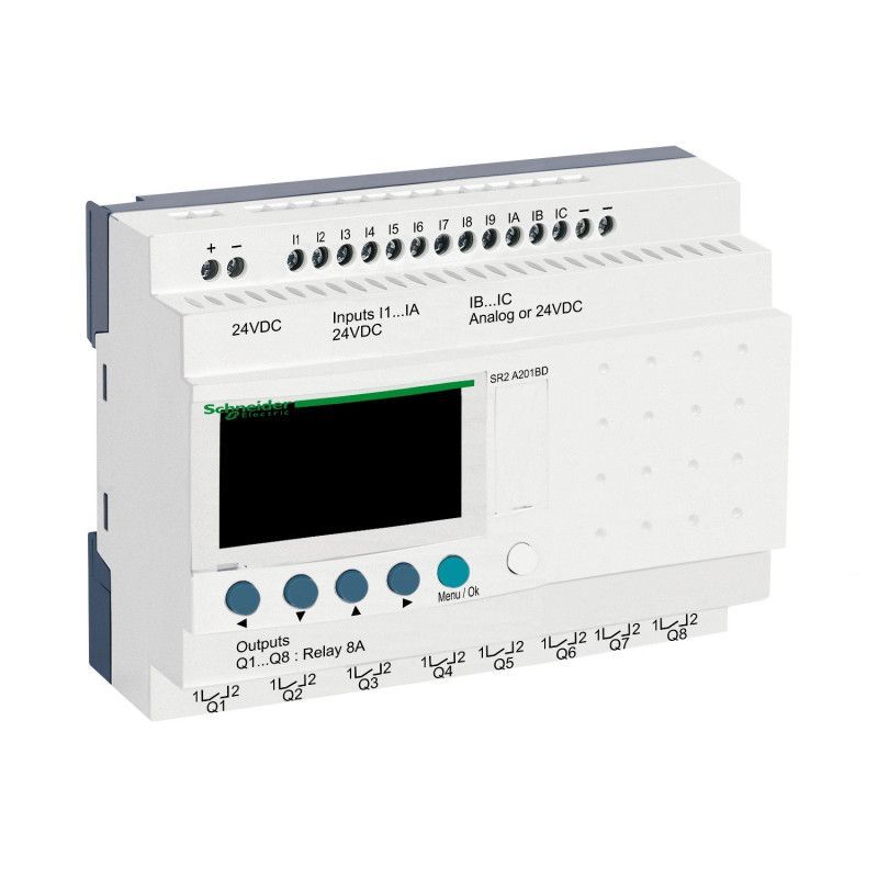
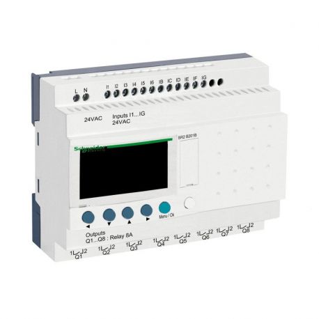
SR2A201BD - Zelio Logic - 20 E/S 24Vcc - sans horloge avec afficheur
2 376,00 MAD
SR2A201BD
New product
Expédition express jour ouvrable suivant
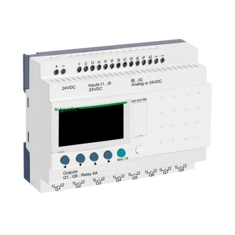
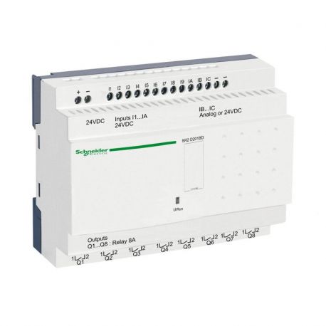
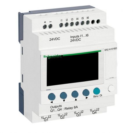
Zelio Compact 20 input output relay - 24 VDC/h2 power supply>The SR2A201BD intelligent relay from Schneider Electric is a programmable logic controller that is easy to implement. It is easily programmed using the Zelio Soft 2 software and its intuitive interface. Easy to install, this Zelio Logic Relay mounts on a standard symmetrical DIN rail. All PLC inputs and outputs are equipped with a screw terminal block. The Zelio SR2A201BD reference is a Compact model, which means that it cannot be associated with an input/output expansion module. If you are looking for a scalable Zelio relay, prefer the Modular model which can accommodate different extension modules. This Zelio PLC is equipped with a digital display screen but does not have a clock. Supply voltage: 24 VDC Inputs and outputs total: 20 Digital inputs: 12 including 0-10V analog inputs: 2 Relay outputs: 8 Transistor outputs: 0 Backlit display screen: Yes Clock: Noi
- Write a review
Main characteristics of the Zelio Schneider PLC reference SR2A201BD: Range: Zelio Logic Type of product or equipment: Compact intelligent relay Additional local display: With number of control diagram lines: 0?240 with ladder programming cycle time: 6? 90 ms backup time: 10 years at 25 °C Clock drift: 12 min/year at 0?55 °C6 s/month at 25 °C checks: Program memory at each power-up [Us] voltage d power supply: 24 V DC Limits of the supply voltage: 19.2?30 V maximum supply current: 100 mA (without extension) power dissipated in W: 6 W without extension reverse polarity protection: With number of digital inputs: 12 comply with EN/IEC 61131-2 type 1 Digital input type: Resistive digital input voltage: 24 V DC digital input current: 4 mA counting frequency: 1 kHz for digital input guaranteed state 1 voltage: >= 15 V for digital input circuit I1 to IA and IH to IR>= 15 V for IB to IG used as digital input circuit guaranteed state 0 voltage: <= 5 V for digital input circuit I1 to IA and IH to IR<= 5 V for IB to IG used as digital input circuit current state 1 guaranteed: >= 1.2 mA (IB to IG used as digital input circuit) >= 2.2 mA (input circuit digital I1 to IA and IH to IR) current state 0 guaranteed: <= 0.5 mA (IB to IG used as digital input circuit) digital input compatibility: 3-wire PNP proximity switches for digital input Number number of analog inputs: 2 Analog input type: Common mode Analog input range: 0...24 V0...10 V maximum admissible voltage: 30 V for analog input circuit Analog input resolution: 8 bits least significant bit value: 39 mV for analog input circuit conversion time: Intelligent relay cycle time for analog input circuit conversion error: +/- 5% at 25 °C for input circuit analog +/- 6.2% at 55°C for analog input circuit repetition accuracy: +/- 2% at 55°C for analog input circuit operating range: 10 m between stations, with shielded cable (non-isolated sensor) for analog input circuit input impedance: 12 kOhm for IB to IG used as analog input circuit12 kOhm for IB to IG used as digital input circuit7.4 kOhm for digital input circuit I1 to IA and IH to IR Number of outputs: 8 relays output voltage limits: 24...250 V AC (relay output) 5...30 V DC (relay output) contact description: "F" for relay output output thermal current: 8 A for the 8 outputs for relay output electrical life: AC-12: 500000 cycles at 230 V, 1.5 A for relay output conforming to EN/IEC 60947-5-1AC- 15: 500000 cycles at 230 V, 0.9 A for relay output conforming to EN/IEC 60947-5-1DC-12: 500000 cycles at 24 V, 1.5 A for relay output conforming to EN/IEC 60947- 5-1DC-13: 500000 cycles at 24 V, 0.6 A for relay output conforming to EN/IEC 60947-5-1 switching capacity in mA: >= 10 mA at 12 V (relay output) availability rate in Hz: 0.1 Hz (at nominal current) for relay output 10 Hz (at no load) for relay output mechanical life: 10000000 cycles for relay output [Uimp] rated impulse withstand voltage: 4 kV conform to EN/ IEC 60947-1 and EN/IEC 60664-1 clock: Without response time: 10 ms (from phase 0 to phase 1) for relay output5 ms (from phase 1 to phase 0) for relay output Connection method: Screw terminals , 1 x 0.2 to 1 x 2.5 mm² (AWG 25 to AWG 14) semi-solid Screw terminals, 1 x 0.2 to 1 x 2.5 mm² (AWG 25 to AWG 14) solid Screw terminals, 1 x 0.25 to 1 x 2.5 mm² (AWG 24 to AWG 14) flexible with end Screw terminals, 2 x 0.2 to 2 x 1.5 mm² (AWG 24 to AWG 16) rigid Screw terminals, 2 x 0 .25 to 2 x 0.75 mm² (AWG 24 to AWG 18) flexible with end Tightening torque: 0.5 N.m Overvoltage category: III conforming to EN/IEC 60664-1 Product weight: 0.38 kg
| Gamme | Zelio Logic |
| Famille | Compact |
| supply voltage | 24 VDC |
| Horloge | SANS |
| Afficheur | AVEC |
| Nombre d'entrées / sorties | 20E/S |
| Nombre d'entrées TOR | 12 |
| Nombre d'entrées analogiques 0-10V | 2 |
| Nombre de sorties à relais | 8 |
| Diametre | 1508.91 |
25 products in category:
In stock
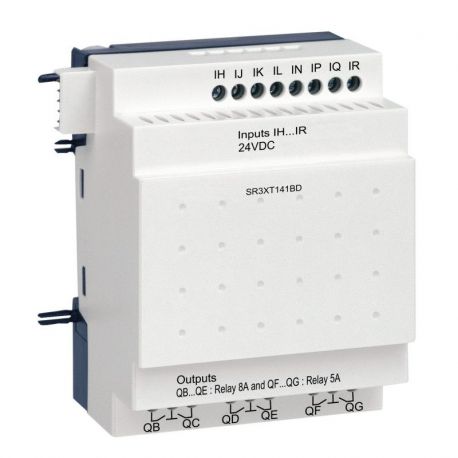
SR3XT141BD Zelio Logic - module d'extension E/S TOR - 14 entrées/sorties - 24Vcc
1 368,00 MAD
0 Review(s)
In stock
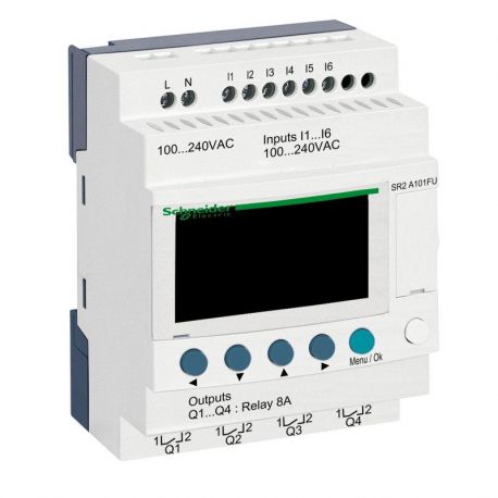
SR2A101FU - Zelio Logic - 10 E/S 100 à 240Vca - sans horloge avec afficheur
1 944,00 MAD
0 Review(s)
In stock
SR2D101FU - Zelio Logic - 10 E/S 100 à 240Vca - sans horloge sans afficheur
1 656,00 MAD
0 Review(s)
In stock
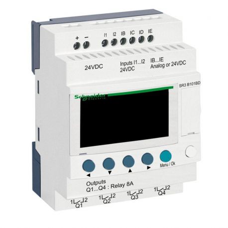
SR3B101BD - Zelio Logic - 10 E/S extensibles - 24Vcc - horloge + afficheur
2 160,00 MAD
0 Review(s)
In stock
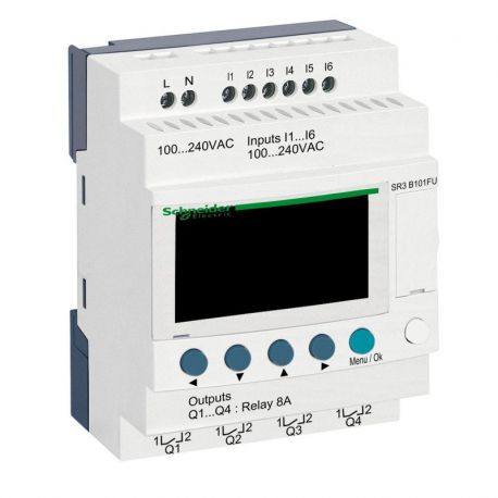
SR3B101FU - Zelio Logic - 10 E/S extensibles - 100 à 240Vca - horloge + afficheur
2 160,00 MAD
0 Review(s)
In stock
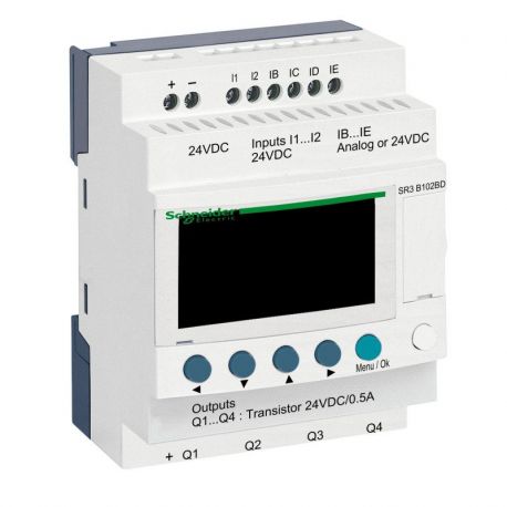
SR3B102BD - Zelio Logic - 10 E/S extensibles - 24Vcc - horloge + afficheur
2 160,00 MAD
0 Review(s)
In stock
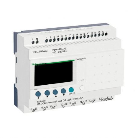
SR3B261FU - Zelio Logic - 26 E/S extensibles - 100 à 240Vca - horloge + afficheur
3 457,16 MAD
0 Review(s)
In stock
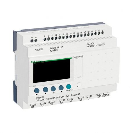
SR3B261JD - Zelio Logic - 26 E/S extensibles - 12Vcc - horloge + afficheur
3 744,58 MAD
0 Review(s)
In stock
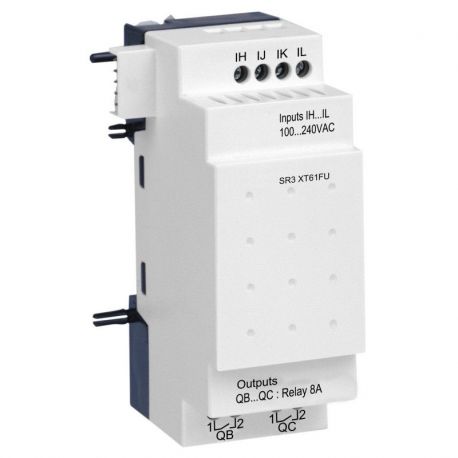
SR3XT61FU - Zelio Logic - module d'extension E/S TOR - 6 entrées/sorties - 100 à 240Vca
864,00 MAD
0 Review(s)
In stock
SR3PACKBD - Zelio Logic - pack découverte - 10 E/S extensibles - 24Vcc
2 808,00 MAD
0 Review(s)
In stock
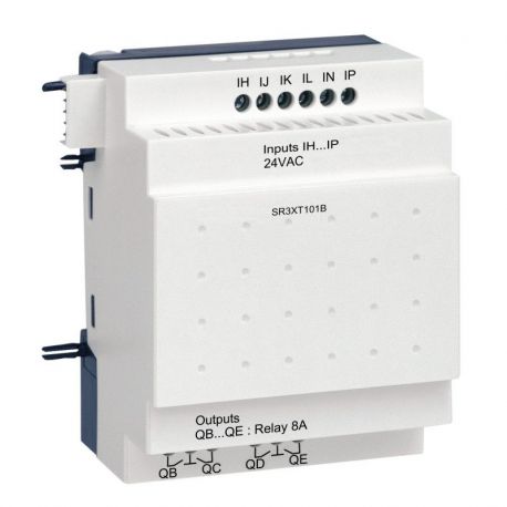
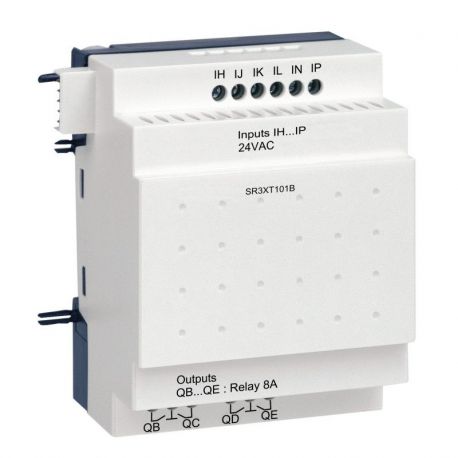
SR3XT101B - Zelio Logic - module d'extension E/S TOR - 10 entrées/sorties - 24Vca
1 080,00 MAD
0 Review(s)
In stock
SR3XT101BD - Zelio Logic - module d'extension E/S TOR - 10 entrées/sorties - 24Vcc
1 080,00 MAD
0 Review(s)
In stock
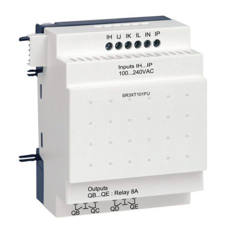
SR3XT101FU - Zelio Logic - module d'extension E/S TOR - 10 entrées/sorties - 100 à 240Vca
1 080,00 MAD
0 Review(s)
In stock
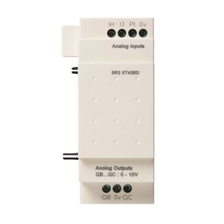
SR3XT43BD - Zelio Logic - module d'extension E/S analogique - 4 E/S - 24Vcc
1 584,00 MAD
0 Review(s)
In stock
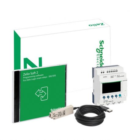
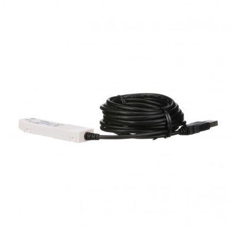
SR2USB01 Schneider Zelio Logic - USB PC connection cord - Zelio PLC programming - 3m
0,00 MAD
0 Review(s)

